Series vs Parallel, Measuring
Circuits
series & parallel |
measuring
Series & Parallel
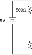
A series circuit has components "one after the other"
so that the same current goes through them all.
 |
|
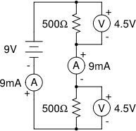
This circuit has two resistors in series. The same current flows
through both resistors. Voltmeters (each placed in parallel with
a resistor) show that both resistors have the same voltage drop
across them, and therefore have the same value. |
|
 |
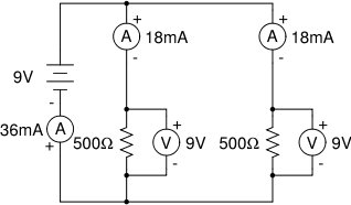
A parallel circuit has the components "side by side"
so that the total current has to split to go through them.
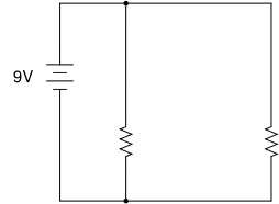
This circuit has two resistors in parallel. The battery provides
a total of 36mA. Because the resistors have the same value the current
splits equally between them. |
|
 |
Measuring circuits
Current is measured with an ammeter.
Symbol (A) [an A in a circle] in the above circuit diagrams.
An ammeter is connected in series, to measure the current flowing
through a particular point in the circuit. An ideal ammeter will have
no resistance so no voltage will be dropped across the ammeter, which
would affect the current flowing through the circuit. In practice ammeters
do have a small amount of resistance, and ammeter leads also have their
own resistance.
A galvanometer
is a type of ammeter.
Voltage is measured with a voltmeter.
Symbol (V) [a V in a circle] in the above circuit diagrams.
A voltmeter is connected in parallel with the component it is measuring
the voltage drop across. An ideal voltmeter will have infinite resistance
so no current flows through the voltmeter instead of where it should go
– through the component it is connected across.
Resistance is measured with an ohmmeter.
The ohmmeter uses a small known current to measure the voltage drop across
a component or circuit.
Using Ohm's Law (V = IR) we only need to know any two out of voltage,
current and resistance to be able to work out the third.
A multimeter
can be used to measure all the above by selecting the desired option with
a rotary switch.
|